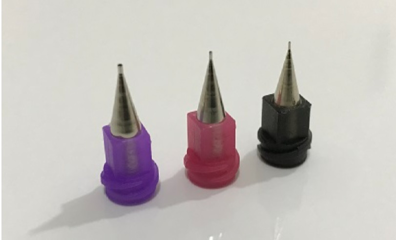
Microfluidic Nozzles: Precision at the Microscale

A microfluidic nozzle moves and shapes fluid inside channels measured in tens or hundreds of micrometers. At that scale, surface tension and viscosity dominate over gravity and inertia, so the nozzle geometry and the way it meets the channel decide whether a process is stable or erratic. What Microfluidic Nozzles Do Microfluidic nozzles interface external fluid handling with a microchannel network. They introduce samples and reagents, deliver metered volumes into a device, form droplets or jets, and collect product at the outlet. Because the volumes are tiny and the channels are fragile, the nozzle must seal reliably, avoid dead volume where fluid stagnates, and not shear or contaminate what passes through it. Types of Microfluidic Nozzle Blunt-tip nozzles. Gentle fluid transfer into and out of channels with minimal disturbance; the default for device filling and assembly. Tapered and drawn nozzles. A narrowing bore raises exit velocity and produces fine jets, useful for injection into a small port. Multi-channel nozzles. Several bores in one body deliver or withdraw multiple fluids at once, raising throughput on parallel devices. Coaxial nozzles. One fluid stream inside another, the standard way to generate monodisperse droplets or core-shell structures for encapsulation and particle synthesis. Custom geometries. Bore, taper, and face angle tailored to a specific channel and connection standard. Key Benefits Precise handling of microliter and nanoliter volumes with good run-to-run repeatability. Low fluid consumption, which matters when reagents or specialty materials are expensive. Higher throughput through multi-channel and automated configurations. Reproducibility, because a stable nozzle-to-channel interface removes a major source of variability. Applications Microfluidic nozzles support analytical instrumentation, chemical synthesis in microreactors, materials research, environmental and process monitoring, and the assembly of the microfluidic devices themselves. Coaxial and flow-focusing nozzles are widely used to produce uniform emulsions and microparticles for coatings, catalysts, and functional materials. In device manufacturing, clear UV-curable adhesive bonds the channel layers and seals the ports; our comparison of UV adhesive and epoxy for transparent bonding covers the material trade-offs. Selecting a Microfluidic Nozzle Material. Chemical inertness against the working fluids and adequate stiffness are the first filters. Stainless steel, borosilicate glass, PEEK, and ceramic are common. Match the material to the harshest solvent in the process. Bore and tip geometry. Inside and outside diameter must suit the channel dimensions and the target flow rate. A tip too large will not seat in the port; a tip too small raises back-pressure and can starve the channel. Fluid compatibility. Confirm the fluid will not swell, dissolve, or react with the nozzle, and that particulates or gels in the fluid are smaller than the bore to avoid clogging. Connection standard. The fitting must mate leak-free with the device or manifold. Dead volume at the junction causes carryover between samples, so choose a low-dead-volume connection. Cleanability. Nozzles that see viscous or curable fluids need a defined flush and, where required, a bake-out or solvent-soak routine. If you are bonding or sealing microfluidic devices and want help choosing an adhesive and a dispensing approach, Email Us…

Comments Off on Microfluidic Nozzles: Precision at the Microscale

Micro Dispensing Nozzles: Precision Fluid Control for Manufacturing

A micro dispensing nozzle places a controlled volume of fluid, often measured in microliters or nanoliters, exactly where it belongs. In adhesive assembly, coating, and encapsulation work, that control is the difference between a repeatable process and one that fights rework every shift. What a Micro Dispensing Nozzle Does Conventional dispensing tips handle drops and beads at the microliter scale and above. Micro dispensing nozzles work an order of magnitude finer, delivering the small, precisely metered shots needed when a few tenths of a millimeter of placement error or a few percent of volume variation would push a part out of spec. They are core hardware in electronics assembly, optical component bonding, sensor manufacturing, and precision coating. Key Features Volume control. Tight repeatability on shot size, so every bond line or dot carries the same amount of adhesive. Small feature size. Fine bore and tip geometry produce narrow beads and small dots for dense assemblies. Dispensing mechanism. Pneumatic time-pressure, positive-displacement auger or piston, and jetting valves each suit different fluids and rates. Jetting, which fires discrete droplets without the tip touching the part, is common for high-speed non-contact work. Material compatibility. Stainless steel, hardened tool steel, and polymer or ceramic-lined bores are chosen to resist abrasion from filled adhesives and to avoid reacting with the fluid. System integration. Nozzles mount to automated dispensing platforms and robots for programmed paths and consistent standoff. Selecting the Right Nozzle Fluid properties. Viscosity, thixotropy, filler content, and pot life drive the choice. A low-viscosity UV adhesive wicks and needs a fine bore with anti-drip control; a filled thermal epoxy is abrasive and needs a wear-resistant bore and a larger inside diameter to avoid clogging. Shot size and rate. The target volume per shot and the shots per minute set the bore diameter and the dispensing technology. Undersized bores raise pressure and cause spitting; oversized bores lose placement precision. Bead or dot geometry. The finished feature width dictates tip inside diameter and standoff height. As a starting point, bead width runs close to the tip inside diameter at a standoff of one to two tip diameters. Standoff consistency. Contact dispensing depends on a fixed gap between tip and part. A robot with height sensing or a mechanical stop holds it; without that, volume transferred varies with every part. Abrasion and clogging. Filled and fast-curing fluids attack nozzles. Plan tip replacement intervals and purge cycles, and keep UV-curable fluid shielded from stray light at the tip, since a partial cure inside the bore ends its life immediately. If you want help matching a nozzle and dispensing method to a specific adhesive, Email Us with the fluid data sheet and the feature you need to place. Where Micro Dispensing Is Used Electronics assembly. Underfill, dam-and-fill, conformal coating edge sealing, and component tacking, where dots must land between closely spaced parts. Optical assembly. Bonding lenses, prisms, and fiber terminations with clear UV adhesive; our comparison of UV adhesive and epoxy for transparent bonding covers material choice. Sensor and…

Comments Off on Micro Dispensing Nozzles: Precision Fluid Control for Manufacturing

Microfluidic Needles: Precision Delivery Solutions | Incure

Need precise fluid handling for your microfluidic applications? Discover the power of microfluidic needles and learn how to select the optimal tool for your research or manufacturing needs. What are Microfluidic Needles? Microfluidic needles are specialized tools designed for the controlled delivery and extraction of fluids in microfluidic channels. Unlike traditional needles, these micro-needles operate at extremely small scales, enabling precise manipulation of minute volumes of liquids. They are essential for interfacing with microfluidic devices, allowing for sample introduction, reagent delivery, and product collection. Types of Microfluidic Needles: Microfluidic needles come in various designs, each tailored for specific applications: Sharp-Tip Needles: Designed for piercing membranes or tissues for targeted delivery or extraction. Often used in biological applications. Blunt-Tip Needles: Ideal for gentle fluid handling within microchannels, minimizing the risk of damage. Common in microfluidic device assembly. Multi-Channel Needles: Allow for simultaneous delivery or extraction of multiple fluids, increasing throughput and efficiency. Used in high-throughput screening. Custom-Designed Needles: Tailored to meet the unique requirements of specific microfluidic applications. Key Benefits of Microfluidic Needles: Precise Fluid Handling: Enables accurate and controlled manipulation of microliter and nanoliter volumes. Minimized Sample Consumption: Reduces reagent and sample usage, saving costs and resources. Enhanced Throughput: Multi-channel needles and automated systems can significantly increase processing speed. Improved Accuracy: Consistent and reliable fluid delivery leads to more accurate and reproducible results. Versatile Applications: Adaptable to a wide range of microfluidic applications across various industries. Applications of Microfluidic Needles: Microfluidic needles find applications in diverse fields: Drug Delivery: Targeted delivery of drugs to specific cells or tissues. Diagnostics: Sample introduction and handling for microfluidic-based diagnostic assays. Cell Sorting: Precise manipulation and sorting of individual cells. Chemical Synthesis: Controlled delivery of reagents for microscale chemical reactions. Microfluidic Device Assembly: Interfacing with microfluidic chips and devices. Selecting the Right Microfluidic Needle: Choosing the appropriate microfluidic needle is crucial for optimal performance. Key factors to consider include: Needle Material: Biocompatibility, chemical inertness, and mechanical strength are important considerations. Common materials include stainless steel, glass, and polymers. Needle Diameter: The inner and outer diameter of the needle should be compatible with the microchannel dimensions and the desired flow rate. Tip Design: The needle tip design (sharp, blunt, multi-channel) should be selected based on the specific application. Connection Type: The connection interface should be compatible with the microfluidic system. Sterility: Sterile needles are essential for biological and medical applications. Working with Microfluidic Needles: Best Practices: Proper Handling: Handle needles with care to avoid damage or contamination. Cleaning and Maintenance: Regular cleaning and maintenance are essential for preventing clogging and ensuring optimal performance. Sterilization: Sterilize needles as needed for biological and medical applications. Compatibility: Ensure compatibility between the needle material, the fluids being used, and the microfluidic device. Conclusion: Precision at the Microscale Microfluidic needles are indispensable tools for professionals and manufacturers working in the field of microfluidics. Their ability to precisely manipulate fluids at the microscale opens up new possibilities for research, development, and manufacturing across various industries. By carefully selecting the right needle…

Comments Off on Microfluidic Needles: Precision Delivery Solutions | Incure

UV Curing Systems: Accelerating Manufacturing with Eco-Friendly Technology

UV curing does two things at once for a production line: it compresses the cure step from minutes to seconds, and it removes solvent from the process. The result is higher throughput on a smaller footprint with no volatile organic compound emissions to manage. The Process A UV-curable coating, adhesive, or ink is a liquid blend of monomers, oligomers, and a photoinitiator. Ultraviolet light of the matched wavelength activates the photoinitiator, which starts cross-linking. The liquid becomes a solid polymer network within seconds, with no heat input and nothing evaporating. Because the material only reacts when exposed, it stays workable on the part until the operator or the line is ready. Why It Speeds Up Manufacturing Cure time. Surface-to-solid in one to ten seconds under adequate irradiance, against many minutes in an oven. No dwell. There is no oven mass to heat and hold and no cool-down before the next step. In-line fit. A correctly sized lamp cures at the same pace a dispensing or coating head places material, so the cure step stops being the bottleneck. Immediate handling. Parts come off cured, ready for assembly or packing. Why It Is Cleaner Typical UV formulations are 100 percent solids. There is no solvent carrier, so there are no VOC emissions, no solvent recovery, and a lighter ventilation load. LED sources add to this by drawing a fraction of the power of a thermal line and generating far less waste heat, which reduces the plant cooling burden as well. Choosing a System Wavelength. Match the source to the resin's photoinitiator. LED systems use a single peak of 365, 385, 395, or 405 nm; broadband arc lamps cover the near-UV band at once. The data sheet dictates the choice. Irradiance and dose. Dose (mJ/cm²) is irradiance (mW/cm²) times exposure time. Specify irradiance at the part surface, not at the emitter, because it falls off sharply with distance. Lamp type and configuration. Flood heads for area coverage, spot systems for localized bonds, conveyors for continuous flow. The Incure L-Series UV LED flood lamps map curing area to intensity across a wide range. Part handling. Low volume and prototyping suit an enclosed chamber that contains the light for safe batch work. High volume points to the Incure CDM UV conveyor, where dose becomes a belt-speed setting. If you want help mapping these variables to a specific line, Email Us with the resin data sheet and your cycle-time target. Applications UV curing systems serve coatings and inks in printing and packaging, conformal coatings and bonds in electronics, finishes and adhesives in automotive and appliance work, encapsulants in renewable-energy module assembly, and resin cure in additive manufacturing. For assembly work where the bond competes with fast handling, our comparison of UV adhesive and epoxy for quick repairs shows where each method fits. Our guide to selecting a UV lamp for resin curing covers source selection in detail. Process Control Read the required dose and wavelength from the data sheet. Measure irradiance at the part with a…

Comments Off on UV Curing Systems: Accelerating Manufacturing with Eco-Friendly Technology

When to Replace Your UV Bulb: Signs and Solutions

Every UV source loses output as it ages, and the drop is invisible because the light itself is invisible. Waiting for a bulb to fail outright means running an undercure risk for weeks first. The better approach is to watch a short list of indicators and replace on evidence, not on a guess. 1. Measured Output Has Dropped The definitive sign is a radiometer reading below the process minimum. UV bulbs typically fade gradually, and many arc lamps are considered end-of-life when irradiance falls to around 70 percent of the new value. If you take a reading at the part surface each week and log it, the decay curve tells you when replacement is due before any part fails. Without a radiometer, you are relying on defects to tell you, which is far more expensive. Our note on what causes UV light guide degradation over time covers how the delivery optics contribute to the same loss. 2. Visible Discoloration or Deposits Inspect the bulb envelope when it is cool. An arc bulb that has darkened, developed a brown or grey film, or shows a milky devitrified patch on the quartz has lost transmission and is near the end of its life. A blackened band near an electrode indicates electrode erosion from too many restarts. LED emitter windows can yellow or haze from heat and stray adhesive vapor, which also cuts output. 3. Physical Damage Any crack, chip, or bubble in a bulb envelope calls for immediate replacement. A cracked quartz arc bulb can fail violently when hot. Check the seals at each end for looseness. On LED heads, look for lifted or discolored lens material over individual emitters. 4. The Lamp Has Exceeded Its Rated Hours Manufacturers publish a rated life in hours for a reason. Once a bulb passes it, output is below spec even if the lamp still lights. Track run hours with the controller's counter or a simple log and replace proactively at the rating rather than pushing past it. 5. Rising Energy Use or Erratic Behavior An arc lamp that flickers, is slow to strike, or dims and brightens has an electrode or ballast problem and will not last. If the same curing step suddenly draws more current or the controller reports faults, the source is deteriorating. If you see these signs and are not sure whether the bulb, the ballast, or the light guide is the cause, Email Us with the lamp model and your radiometer log. What to Do When Replacement Is Needed Order the correct part. Match the bulb to the fixture and ballast by part number. A near-equivalent bulb can run at the wrong current and fail early or undercure. Handle quartz with gloves. Skin oil on an arc bulb bakes into a hot spot that shortens life. Wipe with the maker's recommended solvent before first use if handled bare. Reset the hour counter so the next replacement interval is accurate. Re-measure irradiance at the part surface with the new bulb and…

Comments Off on When to Replace Your UV Bulb: Signs and Solutions

UV Bulb Keeps Blowing? Common Causes and Solutions

A UV bulb that fails weeks or months early is almost always telling you something about the electrical supply, the ballast, or how the lamp is being run. Random bad luck is rare; repeat failures follow a cause you can find and fix. 1. Power Surges and Voltage Fluctuations The issue. A sudden voltage spike drives excess current through the arc or the LED string and can destroy it in a single event. Even smaller fluctuations, repeated over time, stress the electrodes of an arc lamp and shorten its life. Solutions. Fit a surge protector rated for the lamp's load on the supply line. On sites with a weak or noisy grid, add a voltage stabilizer so the lamp sees a steady input. Check whether large motors or welding equipment share the circuit; if so, move the lamp to its own feed. 2. Faulty or Mismatched Ballast The issue. An arc lamp's ballast regulates the current feeding the tube. If it drifts out of spec, delivers the wrong current, or is the wrong ballast for the bulb, the tube runs hot and fails early. Aging ballasts also develop poor connections that arc internally. Solutions. Inspect the ballast for scorch marks, swollen components, and loose terminals. Confirm the ballast rating matches the bulb exactly, part number to part number. Replace a suspect ballast rather than nursing it; a cheap ballast that kills bulbs monthly is expensive. 3. Incorrect Operation The issue. Running a bulb past its rated hours, cycling an arc lamp on and off frequently, or ignoring warm-up and cool-down requirements all cause premature failure. Arc lamps in particular hate rapid restarts, which erode the electrodes. Solutions. Track lamp hours and replace at the rated interval, not when output visibly drops. Keep arc lamps lit with a shutter controlling exposure instead of switching them. Where the process is genuinely intermittent, switch to a UV LED source, which tolerates unlimited cycling. Our comparison of UV lamp options for resin curing covers the trade-off. If failures continue after checking supply and ballast, Email Us with the lamp model, the failure interval, and a photo of the failed bulb. 4. Thermal and Environmental Stress The issue. An arc bulb runs very hot and depends on airflow to stay within its envelope temperature. A blocked exhaust, a failed cooling fan, or a buildup of dust on the reflector traps heat and drives the bulb past its limit. Cold drafts on a hot bulb can crack the quartz. Solutions. Verify the exhaust blower moves its rated airflow and that ducting is clear. Clean the reflector and bulb envelope on a schedule with lint-free wipes and the solvent the maker specifies, handling quartz only with gloves because skin oil bakes on and creates a hot spot. Shield the lamp from direct drafts. 5. Wiring and Connection Faults The issue. Loose lamp-holder contacts, corroded terminals, or a marginal connector create resistance that heats up, drops voltage unpredictably, and can arc. The bulb sees an unstable supply and…

Comments Off on UV Bulb Keeps Blowing? Common Causes and Solutions

Do UV Lamps Use a Lot of Electricity?

The honest answer is that it depends on the technology. A low-power UV LED module can run a full shift on the energy a household bulb uses in an hour, while a broadband mercury-arc curing lamp can draw several kilowatts continuously. The variables that decide the figure are lamp type, rated wattage, duty cycle, and cooling load. What Drives UV Lamp Power Consumption Lamp technology. Mercury-arc lamps convert electrical power to UV at a modest efficiency and reject the rest as heat and non-useful wavelengths, so a 6-inch arc lamp is often specified at 200 to 240 watts per linear inch, reaching a few kilowatts for a wide head. UV LED arrays convert a much larger share of their input into the target wavelength and run cooler, so an LED flood head covering a similar area typically draws a few hundred watts. Rated wattage. Within a technology, higher output means higher draw. A lamp built for 8,000 mW/cm² pulls more than one built for 2,000 mW/cm² at the same area. Duty cycle. Arc lamps are usually kept lit continuously with a mechanical shutter controlling exposure, because frequent restarts shorten bulb life and require warm-up. That means they consume power even between parts. LED heads switch on and off instantly with no penalty, so on an intermittent line they only draw power during the actual cure. Cooling. Arc systems need exhaust blowers and sometimes chillers; those auxiliary loads add to the total. LED heads need fans or a water loop, a smaller addition. Comparing the Two Families For a line running continuously at high throughput, a broadband arc system and an LED system sized to the same dose can end up closer in total energy than the headline wattages suggest, because the arc lamp does more of the curing work per unit area. For a line that cures in bursts with idle time between, LED wins decisively because it is off when not curing. The Incure L-Series UV LED flood lamps are built for that instant-on pattern, while the Incure F-Series flood lamps serve continuous high-spectrum work. Estimating Your Own Consumption Note the lamp's rated input power in watts. Add auxiliary loads: exhaust blower, chiller, controller. Multiply by hours of actual operation per day. For an always-lit arc lamp, that is the full shift; for an LED head, it is cure seconds times parts per day. Divide by 1,000 for kilowatt-hours, then apply your energy rate. A 300-watt LED head curing for three seconds on 2,000 parts a day uses about 0.5 kWh. A 3-kilowatt arc lamp lit for an 8-hour shift uses 24 kWh plus cooling. The gap is large when the line is not running flat out. If you want help modeling the energy cost of a specific curing step before you buy, Email Us with your part rate and cure requirement. Reducing UV Lamp Energy Use Match the source to the duty cycle. Choose LED for intermittent or indexed lines so the lamp is off between parts. Size…

Comments Off on Do UV Lamps Use a Lot of Electricity?

Is Black Light the Same as UV Light?

Black light is ultraviolet light, but only a narrow slice of it. The bulbs sold as black lights emit long-wave UV-A, the least energetic part of the ultraviolet spectrum, filtered so almost no visible light escapes. That combination is what makes fluorescent materials glow while the source itself looks dim purple. The Ultraviolet Spectrum Ultraviolet is electromagnetic radiation just past the violet end of visible light, with shorter wavelengths and higher photon energy than the light the eye can see. It divides into three bands: UV-A, 315 to 400 nm. Long-wave, lowest energy. This is the black-light band and the band used for the majority of UV curing and fluorescent inspection. UV-B, 280 to 315 nm. Medium-wave, more energetic, the band responsible for sunburn. UV-C, 100 to 280 nm. Short-wave, highest energy. Nearly all absorbed by the atmosphere and used only in shielded industrial equipment. A black light concentrates its output around 365 to 400 nm and uses a dark filter glass, often called Wood's glass, to block the visible tail. The faint glow you see from the bulb is the small amount of violet that leaks through. Why Things Glow Under Black Light Many materials contain fluorophores: molecules that absorb UV photons and re-emit the energy as visible light. Under a black light, the UV-A is invisible but the re-emitted light is not, so treated papers, certain minerals, optical brighteners in detergents, and fluorescent dyes appear to shine against a dark background. Remove the UV and the glow stops instantly, because fluorescence is not stored energy. This effect is the working principle behind UV inspection of coatings and adhesives. A fluorescent tracer is blended into the material so that a UV-A lamp reveals coverage gaps, thin spots, and defects that are invisible under white light. Where Long-Wave UV-A Is Used Coating and adhesive inspection. A doped conformal coating or bond line fluoresces under 365 nm, making full coverage easy to verify. Leak and crack detection. A fluorescent penetrant wicks into surface flaws and lights up under UV-A. Material sorting and authentication. Minerals, plastics, and security marks on documents and packaging fluoresce differently, allowing rapid separation or verification. Curing. UV-A drives the photoinitiators in many industrial resins; see our guide to selecting a UV lamp for resin curing. Entertainment and display. Stage and venue lighting uses the same band for visual effect. The light guides that carry UV energy in industrial spot systems are built around this band; our explainer on what a light guide does in a UV spot lamp system covers the delivery side. Black Light Sources Fluorescent black-light tubes use a phosphor that emits around 365 nm behind Wood's glass. Inexpensive and wide-area, but low intensity. LED black lights emit a narrow peak, commonly 365, 385, or 395 nm. A true 365 nm LED gives the cleanest fluorescence with the least visible contamination; 395 nm LEDs are cheaper but leak more violet, which washes out faint fluorescence. Mercury-arc lamps produce a strong 365 nm line among other…

Comments Off on Is Black Light the Same as UV Light?

UV Curing Conveyor Systems: Streamlining Production with Precision

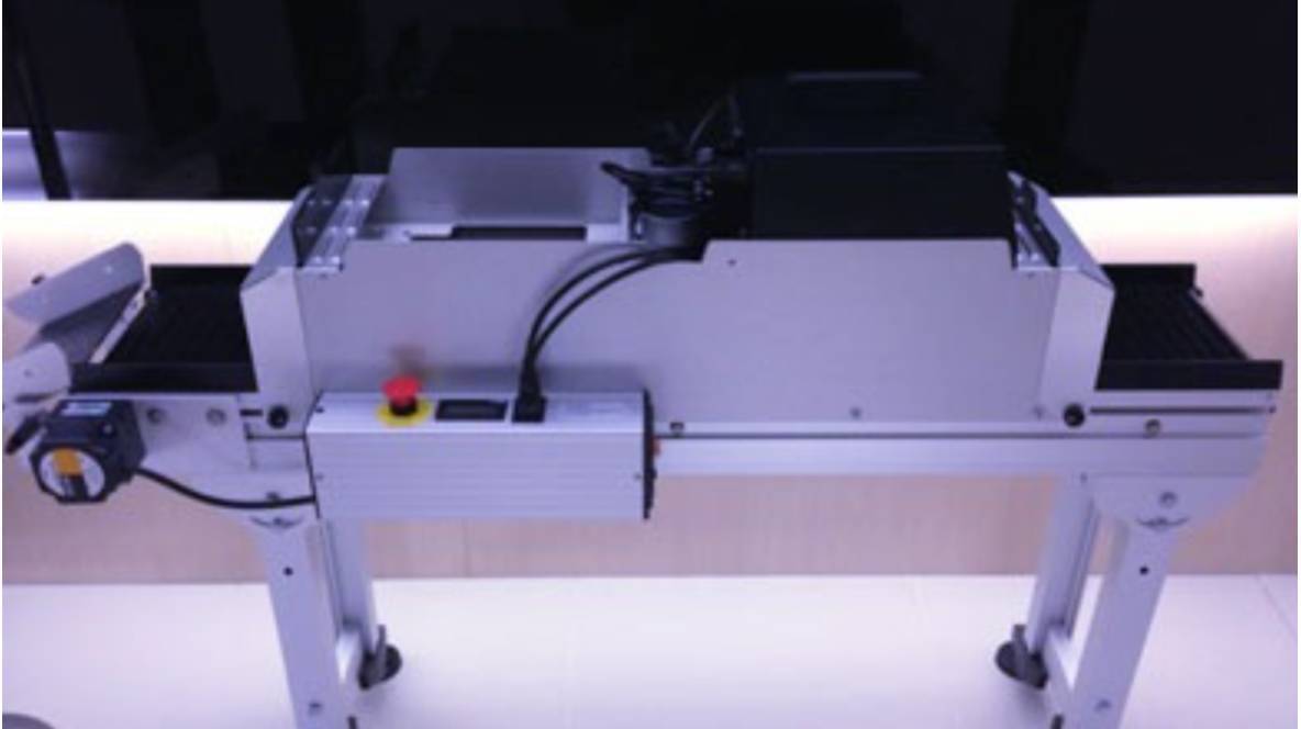
A UV curing conveyor turns a batch operation into a continuous one. Parts ride a belt through an illuminated tunnel, each receiving an identical dose set by belt speed. The result is uniform cure at production rate with no operator handling between placement and finished part. Why a Conveyor Changes the Economics Batch curing means loading a tray, exposing it, unloading, and repeating. Every cycle carries handling time and a risk of misplacement. A conveyor removes those steps. Once the required dose is known, the belt speed is set so that any point on a part spends exactly long enough under the lamp, and throughput becomes predictable: parts per minute equals belt speed divided by part pitch. Consistency improves as well. On a conveyor, every part passes the same lamps at the same speed and distance, so cure variation between the first and last part of a shift is minimal. The Incure CDM UV conveyor matches lamp head type and belt width to part size and line speed. Key Benefits Continuous flow. No downtime between batches; the line feeds cure and cure feeds the next step. Uniform dose. Fixed geometry and speed give repeatable hardness, adhesion, and chemical resistance. Lower labor. Parts are placed once and come out cured. Energy efficiency. UV cure draws far less power than a thermal tunnel of equivalent throughput, and LED heads draw less still. Scalable dose. Adding lamp heads along the tunnel lets the belt run faster at the same dose. Selecting a Conveyor System Lamp head. LED heads run cool, switch instantly, and hold output for tens of thousands of hours; the Incure L-Series UV LED flood lamps are a common choice. Broadband arc heads such as the Incure F-Series flood lamps suit resins that need the wider spectrum or a very high peak irradiance. Wavelength. Match the LED peak or arc spectrum to the resin photoinitiator, confirmed against the data sheet. Belt width and material. The belt must carry the maximum part size with clearance and tolerate the UV and heat without degrading. Mesh belts allow some light to reach the underside; solid belts do not. Belt speed range. Confirm the drive can run slow enough for the worst-case dose and fast enough for the target rate. Cooling and exhaust. LED heads need heat-sink airflow; arc heads need ducted exhaust for heat and any ozone. If you want help converting a cure dose into a belt-speed and lamp-count specification, Email Us with the resin data sheet and your throughput goal. Setting the Dose Read the required dose (mJ/cm²) and peak wavelength from the resin data sheet. Measure the tunnel's irradiance at belt height with a conveyor-style radiometer that logs the full profile as it passes. Calculate the exposure time as dose divided by average irradiance. Set belt speed so residence time under the illuminated band equals or slightly exceeds that exposure time. Verify cure on sample parts with a hardness or adhesion check. Re-run the radiometer weekly to catch output decay. Common…

Comments Off on UV Curing Conveyor Systems: Streamlining Production with Precision

UV Curing Systems: Accelerating Production and Enhancing Quality

UV curing replaces minutes or hours of thermal drying with a photochemical reaction that finishes in seconds. For coatings, adhesives, inks, and encapsulants, that shift compresses cycle time, tightens quality control, and removes solvent from the process. The Photochemistry A UV-curable formulation is a blend of liquid monomers and oligomers with a photoinitiator. When ultraviolet light of the right wavelength strikes the photoinitiator, it generates reactive species that trigger cross-linking. The liquid becomes a solid polymer network almost immediately, with no heat input and no evaporating carrier. Because the reaction is light-driven rather than time-driven, the material stays workable until the moment of exposure. What a UV Curing System Delivers Rapid cure. Surface-to-solid transitions in one to ten seconds under adequate irradiance, against many minutes for oven curing. Consistent finish. A fixed dose produces the same hardness, adhesion, and chemical resistance on every part. Lower energy use. No oven to heat and hold; LED sources in particular draw a fraction of the power of a thermal line. No solvent. Typical formulations are 100 percent solids, eliminating volatile organic compounds and the ventilation load that comes with them. Broad substrate range. Coatings and adhesives for glass, metal, and many plastics; our comparison of UV adhesive and epoxy for transparent bonding covers where each fits. Choosing a System: The Core Variables Wavelength. Match the source to the resin. LED systems are built around a single peak of 365, 385, 395, or 405 nm; broadband arc lamps cover the whole near-UV band at once. The photoinitiator in the data sheet dictates the choice. Irradiance and dose. Irradiance (mW/cm²) times exposure time gives dose (mJ/cm²). Specify irradiance at the part surface. A resin needing 2,000 mJ/cm² cures in two seconds at 1,000 mW/cm² or four seconds at 500 mW/cm². Lamp configuration. Flood heads for area coverage, spot systems for localized bonds, conveyors for continuous flow. The Incure L-Series UV LED flood lamps map curing area to intensity across a wide model range. Part handling. A benchtop enclosure suits low volume and prototyping; the Incure B/C-Series UV cure chambers contain the light for safe batch work. High volume points to a conveyor such as the Incure CDM UV conveyor, where dose becomes a belt-speed setting. If you want help mapping these variables to a specific product, Email Us with the resin data sheet and your target cycle time. Integration With the Production Line The value of UV curing multiplies when the cure step matches the pace of the steps around it. A dispensing cell that places a bead in two seconds is throttled by a 30-second cure; a correctly sized lamp brings cure down to the same two seconds and the cell runs at rate. On automated lines, the source should accept a trigger signal, report lamp health, and cycle without warm-up, which favors LED heads over arc lamps for indexed work. Process Control and Validation Validate a UV process the same way regardless of scale: Read the required dose and wavelength from the data…

Comments Off on UV Curing Systems: Accelerating Production and Enhancing Quality